

CGLC60A型溜槽是在我厂引进的美国、俄罗斯溜槽和国内龙江I型溜槽的基础上,吸收其先进结构的优点进行设计制造的,并经过多次生产实验,多次改进后生产定型的。它具备以下各项优点:
1、金矿砂处理量大,每小时可洗选矿砂60 - 80m3/h,砂石≤ 10mm时可达 150 m3/h。
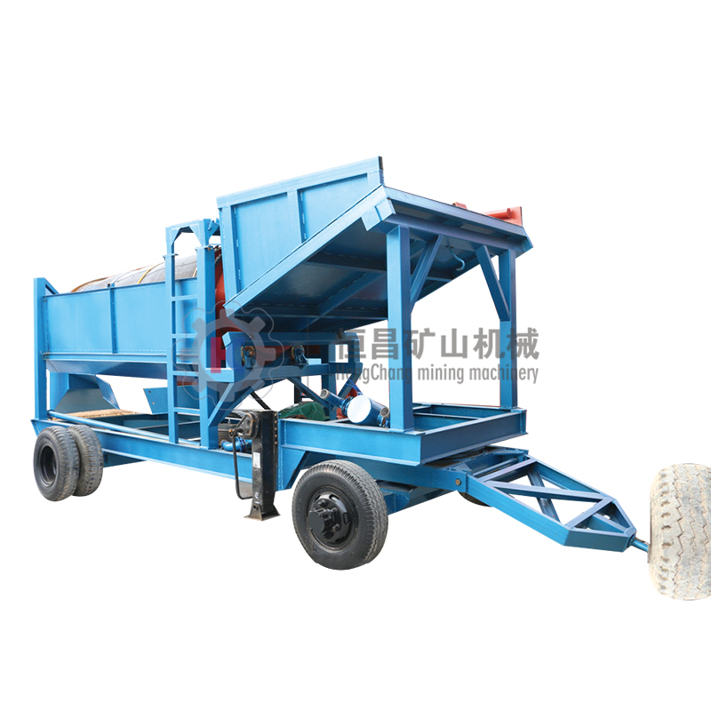
2、结构合理,强度高,可拆装性强,便于运输搬迁。
3、采金回收率高,回收率可达到85-90%,不但能回收粒状金、片状金,还可回收微粒金。
4、适应性很强,可在任何条件的矿体内选矿。
| CGLC60A型双层组合式砂金选矿溜槽技术参数 | ||
| 矿砂处理量 | m3/h | 60-80 |
| 总用水量 | m3/h | 882 |
| 12"寸泵(主喷水管) | m3/h | 792 |
| 4"寸泵 | m3/h | 90 |
| 电机总容量 | kw | 32 |
| 12"寸泵电机功率 | kw | 22 |
| 4"寸泵电机功率 | kw | 7.5 |
| 溜槽长度 | kw | 0.7 |
| 主溜槽 | mm | 5800 |
| 副溜槽 | mm | 7330 |
| 溜槽宽度 | ||
| 主溜槽 | mm | 1000 |
| 副溜槽(上口) | mm | 800 |
| 副溜槽(下口) | mm | 1080 |
| 溜格数 | ||
| 主溜格 | 个 | 9 |
| 副溜格(两边) | 个 | 22 |
| 溜槽安装角 | (°) | 10-12 |
| 塑料毛毡总长 | m | 21 |
| 外形尺寸 | m | 12.3×4×2.2 |
| 总质量 | t | 11 |
1、上料台:是承装矿砂料的部位,也是充分造浆的部位。
2、筛分装置:筛分装置由筛板和大小分流箱组成。
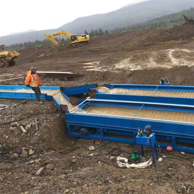
3、溜槽:溜槽分主溜槽、副溜槽。主溜槽在中间,副溜槽分置两侧。是采金选矿的主要部位。
4、溜格:溜格分主溜格、副溜格。主溜槽内放9个主溜格,副溜槽内(每侧)放11个副溜格。
5、底坐:由4根地梁和11根横梁组成,上述三大部件按顺序组装在底座上,组成一台完整溜槽。
6、主喷水管:是采金选矿的水源装置,它由12寸混流泵供水,装在斜筛板上方。
7、副喷水管:补充主喷水管水量,扩大喷水范围,在主喷水管尾部接6寸胶管与副喷水接通,装在方筛板上方。
8、塑料毛毡:铺在主、副溜槽底部,是珍藏砂金的主要部位。
9、电气装置:可用柴油机带动,也可用发电机组,有电路地区,也可用电动机驱动。
10、附属设备:砂金精选机、金砂箱。
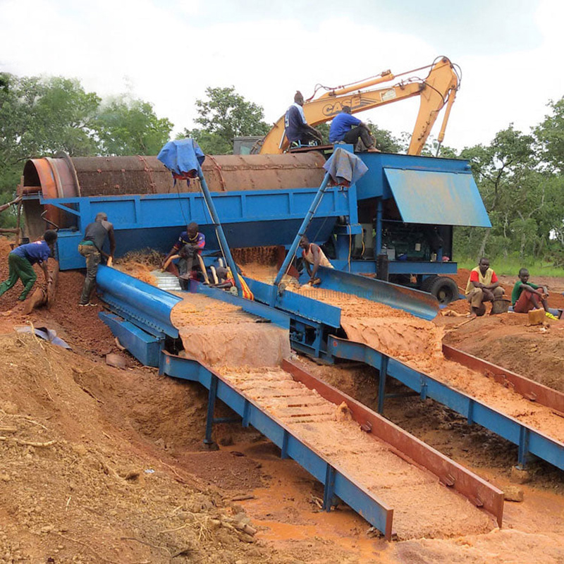
安装位置选定后,用推土机将剥离的非矿砂推成角度为10º-12º,长 14m,宽 5m的坡形基座,上面铺上6-8根枕木,操平,按先后顺序将溜槽组装在座机上,各连接部用螺栓连接,用力把紧。根据砂金颗粒大小和形状,确定溜槽安装角度。当粒状金或以大、中粒为主时,宜坡度稍大,当砂金颗粒小,以片状、微粒金为主时,宜坡度稍小;以保证回收率。溜槽角度确定后,调好定位。
按选定位置安装水泵,并用胶管连接成回路。
安装好动力线和电气操纵装置。
一切准备就绪后,接通电源和水泵进行试溜,试溜成功,就可投入生产。每八小时清溜一次,在清溜前,先停止供料,继续供水,清洗5-10分钟后停水。取出主、副溜格将毛毡上的浮砂收起放入金砂箱,然后将毛毡卷起放入金砂箱抖洗,毛毡洗净后放回溜槽内,继续生产。将金砂箱内的金砂,用锹放入精选机上进行精选,然后经过人工精淘产出砂金。
1、上料台、主、副溜槽各筛板为钢板焊接而成,在供料、推尾砂和搬迁运输中,严防碰撞以防严重变形,造成停产。
2、在洗选中,在额定容量内,主、副槽内必须有足够水,如水量不均或不够,应及时调整水泵,溜槽内的矿浆液固比一般为10-12:1,矿浆流速为1.4 - 1.6米/秒,安装溜槽时,横向应保持水平.
3、溜槽筛板用于矿砂筛分选矿,当筛孔严重堵塞时,应在清溜时及时清除。
4、在洗选中,清溜时间根据实际情况定。当金粒较大时,宜8-10小时清溜一次,当金粒较小或片状时宜6- 8小时清溜一次。
5、溜槽搬迁时,距离远应解体分组搬迁,在新基座上组装,其安装顺序和要求同前。连接螺栓必顺紧固。距离近时,整体搬迁,必顺拉牵引杠,牵引杠穿在地梁两端各孔内,不准牵引其它部位。
CGLC60A Combined Placer Gold Separation Chute is designed and manufactured by assimilating advantages of the advanced structure on the basis of American chute imported by our factory and Longjiang 1 Model Chute in China. It also has undergone many production tests and improvements with its advantages as follows:
A.Large capacity of handling placer gold at a washing capacity of 60 -80m3/h.
B.Rational structure, high strength, removable and easy to be transported and transferred.
C.High recovery in gold mining at a rate of 75-80%, recovering not only granular gold and platelet gold but particulate gold.
D.Strong adaptability and applicable for beneficiation of ore deposits at any conditions.
| CGLC60A Model | ||
| Mineral sand handling capacity | m3/h | 60-80 |
| Overall water consumption | m3/h | 882 |
| 12'' pump(main water spray pipe) | m3/h | 792 |
| 4'' pump | m3/h | 90 |
| Overall capacity of motor | kw | 32 |
| 12'' pump motor power | kw | 22 |
| 4'' pump motor power | kw | 7.5 |
| Sluice length | kw | 0.7 |
| Primary sluice | mm | 5800 |
| Secondary sluice | mm | 7330 |
| Sluice length | ||
| Primary sluice | mm | 1000 |
| Secondary sluice(Upper opening) | mm | 800 |
| Secondary sluice(Lower opening) | mm | 1080 |
| No.of sluice lattice | ||
| Primary sluice lattice | 个 | 9 |
| Secondary sluice(two edges) | 个 | 22 |
| Sluice mounting angle | (°) | 10-12 |
| Overall length of plastic felt | m | 21 |
| Outside dimension | m | 12.3×4×2.2 |
| Overall quality | t | 11 |
A.Feeding platform - section of carrying gold placer materials and place where pulp is fully produced.
B.Screening device – composed of screen plate and separation box.
C.Chute – including primary chute and secondary chute with the primary chute put in place in middle and the secondary chute on both sides; major part of gold mining and separation.
D.Chute – including primary chute and secondary chute with the former housing 9 lattices and the latter containing 11 lattices on every side.
E.Base – made up of 4 ground beams and 11 cross beams, which are mounted on the base in order, forming a complete chute.
F.Main water spraying pipe – water source device for gold mining and separation, composed of 12 in flow blending pump for water supply which is mounted above inclined screen plate.
G.Secondary water spraying pipe – replenishing water volume for the primary water spraying pipe and expanding area of water spraying, connecting with the primary water spray by linking 6 in rubber pipe at its end; mounted above the square screen plate.
H.Plastic felt – covered at the bottoms of the primary and secondary chutes, a main area for storing placer gold.
I.Electrical device – driven by either diesel engine or electrical generator; If electric circuit is available in the area, electrical motor can be used for operation.
J.Auxiliary equipment: placer gold separator and gold placer box.
After the position of installation is selected, stripped waste rock will be pushed by bulldozer to form slope foundation with dip angle 100~120, 14 meters in length and 5 meters in width. 6~8 pieces of timber sleeper are put on the foundation and then leveled. The chute will be assembled on the foundation according to sequences. Each connecting points will be connected with bolts. All bolts must be tightened. The installation angle of chute will be determined according to the size and shape of placer gold particles. The slope of chute should be slightly large, when platelet gold or large and medium particles of placer gold are dominant. The slope of chute should be slightly small, when the platelet and particulate gold and small particles of placer gold are dominant to ensure recovery. After the angle of the chute is determined, the position of the chute will be adjusted.
Water pump should be installed on the position selected, and connected to form return circuit with rubber hose.
Power line and electric operating equipment should be installed properly.
When everything is ready, power supply and water pump will be connected to conduct chute beneficiation experiment. If the experiment is successful, the chute can be used in production. The chute should be cleaned every 8 hours. Before cleaning, feeding should be stopped, and water should be supplied continuously. After cleaning 5~10 minutes, the supply of water should be stopped. Main and auxiliary chute lattices are taken out, and floating sands on the hair felt are collected to the gold sand tank before rolling up the hair felt and putting it into the gold tank for vibrating and washing . After being cleaned, the hair felt is put back into the chute, and is used to produce gold placer again. The gold sand in the gold placer tank will be sent with spade to cleaning machine to product cleaning. Then gold placer will be produced via manual fine elutriation.
A.The plates of feeding platform, primary chute and secondary chute are welded with steel plate and should be protected from collision to avoid deformation during material supply, feeding tailing and transport.
B.During washing, adequacy water in primary chute and secondary chute should be ensured at rated capacity and adjustment of pump should be done timely in case of shortage of water supply. Generally solid-liquid ratio of slurry in the chute is 10~12:1, flow velocity is 1.4~ 1.6 m/s. Lateral of chute should be kept level.
C.Screen plate of the chute is used for screening placer gold. When screen holes are blocked, it should be cleaned timely.
D.In washing, cleaning time of chute is determined according to actual situation. If gold grain is bigger, a cleaning chute per 8~10 h., if gold grain is small or platelet gold, a cleaning chute per 6~8 h.
E.In moving chute for long distance, disassembly moving should be done, assembly on new base should be according to previous installation sequence, jointing bolt must be tightened. If chute is moved in whole unit, drawbar must be used, passing hole in two ends of ground beam, other part of chute can be not drawn.


 English


